
Hydraulic Seal Kit Dimensions and Tolerances: A B2B Validation Guide Before Installation
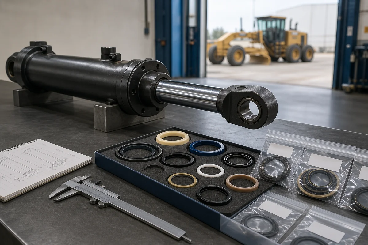
Inside a busy hydraulic repair shop, the moment of truth usually arrives when the kit is opened on the bench: the cylinder is disassembled, the old PTFE piston seal sits beside the replacement, and somebody notices that the new seal measures a fraction of a millimeter different from the one just removed — on the outer diameter, on the cross-section width, or both. A difference of roughly 0.2 mm in PTFE seal dimensions is exactly the kind of observation that appears again and again in technician discussions, because it looks small enough to ignore and feels too important to shrug off. For B2B distributors, hydraulic repair shops, fleet maintenance teams, and procurement staff who buy hydraulic seal kit dimensions matter at order level, the correct response is neither “install it” nor “reject it” on the spot. It is a structured validation decision. This guide explains how to run one before installation: why an outer-diameter or width difference alone cannot prove a seal is usable, which grooves, mating parts, working conditions, and installation risks must be checked, and how to turn the findings into an RFQ, a sample approval, and a batch check that protects a bulk order.
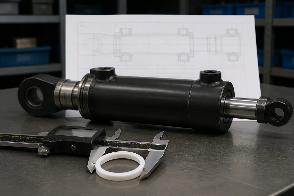
A 0.2 mm difference is a question, not a verdict
Before anything is installed, it is worth understanding why the number on the caliper so often disagrees with the part that came out of the cylinder. A removed PTFE seal has typically spent thousands of hours under pressure, heat, and sliding contact. Its sealing surfaces are worn, its corners are rounded, and the material itself may have relaxed or taken a permanent set. The same profile measured in its free state, on a different instrument, or at a slightly different point on the lip can read differently for reasons that have nothing to do with whether it will seal. On top of that, the old part is not always the correct part: many cylinders have been rebuilt before with aftermarket components of unknown origin, and “matching the old seal” can mean faithfully reproducing an earlier mistake.
The practical consequence is simple. A direct comparison between the removed seal and the replacement is a useful first screening step — it can catch a grossly wrong part number or a visibly different profile family. But it cannot by itself confirm that the replacement will seal, and a small deviation does not automatically condemn it. The reference that matters is the seal groove and the drawing that defines it. That is why the discipline described below treats the removed part as evidence of what the cylinder has been through, and the drawing plus the measured hardware as the authority for what the cylinder needs.
What outer diameter and cross-section width can — and cannot — tell you
Outer diameter and axial width are the two dimensions most buyers can measure without special tooling, which is why they dominate the “will it fit” debate. They are genuinely useful: they confirm that the replacement belongs to the same size family as the removed part and they flag obvious mismatches early. The problem is that a seal does not seal against its own free-state dimensions; it seals because of the relationship between its cross-section and the groove it sits in. Radial interference depends on the groove diameter, not on the outer diameter of the uninstalled part. Axial squeeze depends on the groove width and on how the material behaves at operating temperature and in the system fluid. An OD or width difference can be fully harmless in one groove and fully unacceptable in another, which is why a meaningful hydraulic seal tolerance statement can only be made against a specific groove geometry — never as a general rule of thumb that works for every kit.
| Comparison you perform | What it can reveal | What it cannot reveal | What to do instead |
|---|---|---|---|
| Outer diameter of new seal vs. removed seal | Confirms the same size family; catches a visibly wrong part | Whether radial interference suits the groove, whose diameter controls the fit | Measure the groove diameter and compare the seal against the drawing values |
| Axial width of new seal vs. removed seal | Flags a different profile family if the difference is large | Whether axial squeeze is correct; material swell and thermal effects change installed width | Measure groove width in at least two places and compare with the drawing |
| Corner radii and cross-section shape | Reveals profile families that share a nominal size but differ in geometry | Sealing behavior in a groove machined for another profile shape | Compare the cross-section against the drawing, not only against the old part |
| Single measurement at one point on the part | Fast first check | Ovality of the seal or the groove; variations around the circumference | Take readings at several points roughly 90 degrees apart and record all of them |
| OD and width only, nothing else | A quick pass-fail impression | Wrong material, missing backup clearance, directionality, or an incomplete kit | Complete the full verification sequence in this guide before approving installation |
The table above is the reason this guide exists. A caliper comparison answers one question — “are these two parts in the same size range?” — and it answers it honestly only when the old part is known to have been correct. Every other question about fit, squeeze, and clearance requires a groove, a drawing, or a documented specification to answer.
Validate the groove and the mating parts, not just the seal
The groove is where a seal lives, and the groove is measurable while the cylinder is apart. For each sealing position, measure the axial groove width and the groove diameter at multiple points around the circumference, and record the worst reading. Then measure the running surfaces: the bore diameter and condition where the piston travels, and the rod diameter and surface condition where the rod seal runs. Note out-of-round, taper, scoring, rust, or plating damage. A rod that has worn oval or a barrel that is bell-mouthed at the end of stroke will defeat a dimensionally perfect seal, because the seal cannot compensate for hardware that is no longer round.
Mating parts extend beyond the cylinder hardware itself. If the cylinder uses wear rings or guide rings, their remaining clearance controls how much the piston and rod can tilt under side load — and that tilt directly changes the extrusion gap the seals have to survive. Checking the groove dimensions against the drawing the supplier used is also the fastest way to catch a kit that was built for a different cylinder revision. If you need a reminder of correct measurement technique, instrument choice, and where to place the caliper jaws, our guide to measuring hydraulic seals for replacement walks through the practical steps in detail.
Working direction, profile family, and installation method
Two seals can share almost identical dimensions and still be different products. A rod seal with an asymmetric lip is designed to seal in one direction, and installing it upside down converts a sealing lip into a collection edge that traps contamination and leaks under pressure. Piston seals are often symmetric, but step seals, compact seals, and U-cups each behave differently in the same groove. When a replacement shows a small width difference from the old part, one of the first questions is whether it belongs to the same profile family at all — a nominal-size match across families is common and is exactly what a drawing comparison catches.
Installation risk is part of the dimension decision too. A split or scarf-cut PTFE seal can be fitted into an endless groove, while a continuous ring cannot; forcing the wrong construction damages the sealing surface before the cylinder ever runs. Sharp groove edges, port openings, and keyways can nick a new seal during assembly, and a kit that lacks the backup rings specified for the working pressure will let a soft seal extrude on the first heavy cycle. Check the kit contents against the OEM seal arrangement before assembly, and make sure the person doing the install has the right tooling and knows which direction each part faces.
Material, fluid, temperature, and pressure belong in the same decision
Dimensions describe the geometry of a seal, but a seal works through the interaction of geometry and material behavior. An elastomer seal swells or shrinks in the hydraulic fluid, softens with temperature, and takes a permanent set under sustained pressure; a PTFE-based seal is far more stable dimensionally but still depends on the energizer element and on the filler used in the compound. Virgin PTFE, bronze-filled PTFE, carbon-filled grades, and PTFE elements with an elastomer energizer all look similar on a bench and behave very differently in service. Matching the outer diameter is meaningless if the compound is incompatible with the fleet’s fluid or outside the machine’s temperature range.
For this reason the fit decision must include the working conditions that were never visible on the caliper: fluid type, operating temperature range, maximum pressure, cycle frequency, and any contamination the rod is exposed to. Pressure matters twice — it determines whether backup rings are required and whether an energizer is stiff enough to hold the lip against the surface. Where any of these values is missing from the machine documentation, the RFQ should say so openly and ask the supplier to confirm suitability from the material data sheet, rather than guessing. Our guide to vetting your hydraulic seal supplier describes how to read those data sheets critically instead of accepting them at face value.
Seal kit drawing verification: give every measurement a reference
Seal kit drawing verification is the discipline of confirming kit contents and each seal’s key dimensions against a written reference — an OEM drawing, a supplier drawing, or a documented data sheet — before the kit is approved for installation. It exists because every other comparison in this guide is only as good as the reference it points to. The workflow has four steps. First, ask the supplier for the drawing or dimensional report for each sealing position in the kit, and confirm the revision matches the cylinder. Second, check which values on that drawing are controlled dimensions and how they are defined — for example, whether an outer diameter is measured in the free state, and at which point the width is taken. Third, measure the incoming parts and compare them with those controlled values, not with the removed seal. Fourth, record the results against the batch number so the same check can be repeated on the next order.
A drawing also resolves disputes before they start. When the old part and the drawing disagree, the drawing is the authority — the removed part may be the very component whose failure caused the repair. When no drawing exists for an older or obscure cylinder, ask the supplier to provide one from the kit data and to state in writing which dimensions are controlled and which are informational. That written statement becomes the tolerance reference for the order, which is precisely the gap that a bare “they look close enough” comparison leaves open.
Grading a dimensional deviation before installation
Because deviations are common and rarely identical, B2B buyers should grade them instead of reacting to each one as an emergency. The grading categories below are a starting structure — the actual acceptance values for each part number must come from the drawing and from written agreement with the supplier, not from a general table. What matters is that every deviation is assigned a handling path, so the workshop does not improvise the decision at the bench.
| Deviation observed | Possible causes to investigate | Risk if installed unverified | Recommended handling |
|---|---|---|---|
| Width or OD differs from the drawing by a small amount, such as roughly 0.2 mm on a PTFE profile | Measurement point or technique; legitimate production tolerance stated on the drawing; different profile family; or wrong part | Loose or over-preloaded fit; premature leakage or difficult assembly — but possibly no risk at all | Re-measure at defined points, compare with the drawing, and confirm with supplier before bulk installation |
| Deviation repeats in the same direction across several parts in the batch | Systematic cause such as a tooling setup or material batch difference in production | Whole order is affected consistently; the problem will repeat on every install | Request the batch dimensional report, hold the lot, and confirm with supplier before use |
| Deviation appears randomly, part to part, with no pattern | Mixed batches, mixed materials, or inconsistent measurement on your side | Traceability lost; some parts may be fine while others fail in service | Check batch numbers and packaging, increase the number of parts measured, and confirm with supplier |
| Groove measurements in the cylinder contradict the drawing the kit was made to | Cylinder rebuilt with non-standard parts, wear, or a different cylinder revision | Seal failure regardless of seal accuracy, because the housing itself is off | Send the actual measured groove values to the supplier and confirm with supplier before proceeding |
Notice what this grading does not contain: no universal “acceptable” numbers. A deviation that is trivial in a low-pressure static groove can be critical in a high-pressure rod seal, which is why the acceptance values belong to the drawing and to the written confirmation for that specific part number — not to a generic table that pretends every groove is the same.
The RFQ dimension fields that make validation possible
A supplier can only validate what it is told. When an RFQ for replacement seals carries the fields below, the supplier can select or manufacture against the right reference, state realistic expectations, and flag conflicts before production instead of after delivery. When a field cannot be filled because the machine is old or the documentation is lost, write “confirm with supplier” in that field rather than inventing a number.
| RFQ dimension field | What to record | Why the supplier needs it |
|---|---|---|
| Machine and cylinder identity | Equipment model, cylinder part number and revision, sealing position (rod, piston, static) | Establishes which arrangement drawing and seal family apply |
| Bore and rod diameters | Measured values plus a note on condition (new, worn, out-of-round) | Defines the surfaces the seals must run on and the available radial space |
| Groove dimensions per seat | Axial width and groove diameter, measured in at least two places | These are the controlling features for squeeze and clearance |
| Removed seal measurements | OD, width, and height of the old part, noting whether it is worn | Reference only — supplier will still validate against the drawing |
| Profile code or reference numbers | Any numbers stamped on the old part, or OEM and aftermarket codes from the kit list | Helps map the part to the correct profile family and revision |
| Operating conditions | Fluid type, temperature range, maximum pressure, cycle and stroke information | Drives material selection and the need for backup rings |
| Installation constraints | Whether grooves are endless or open, split seals acceptable, assembly tooling available | Determines seal construction and packaging per position |
| Quantity and documentation | Pieces per kit, number of kits, required dimensional report and batch traceability | Sets the sampling plan and the paperwork attached to the order |
These fields convert a vague “I need seals for this cylinder” into a specification that both sides can verify. They also make the replacement seal kit measurements meaningful: when the values on the incoming parts are compared with the values on the RFQ and the drawing, the comparison has a defensible basis instead of a guess.
Sample acceptance and batch sampling
Before any bulk order, validate samples as first articles for every part number in the kit. Measure each position — outer diameter, width, height, and any dimension the drawing marks as controlled — at defined points and record the values. Where the cylinder is available, do a trial fit: assemble the piston into the barrel and the rod into the gland dry, and feel for binding, excessive looseness, or a seal that rolls out of its groove. Keep the approved sample and its dimensional report on file; it becomes the working reference for the next order and for any later dispute about a batch that measures differently.
Batch sampling follows the same logic at order scale. Before production, agree with the supplier on the sampling routine in writing: how many pieces per batch will be measured, which instrument and measuring points will be used, and what happens when a part falls outside the agreed reference — re-inspection of the whole lot, replacement, or rejection. These terms must be specific to the part and tied to the drawing; they cannot be copied from a general rule. When an incoming batch measurement does fall outside the agreed reference, hold the lot, request the supplier’s own dimensional report, and confirm with supplier before any of it reaches a cylinder. The goal is not to make sampling an adversarial process, but to ensure that a problem surfaces while the parts are still in boxes rather than after they are installed in a customer’s machine.
When the honest answer is “confirm with supplier”
Across every step above, certain findings should stop the process and trigger a written question to the supplier instead of a local decision. Confirm with supplier when: the drawing carries no tolerance statement for a dimension that matters; the material data sheet does not clearly cover the fluid and temperature range on the RFQ; the measured hardware is out-of-round or worn beyond the values you supplied; the profile family of a replacement is unclear even though the nominal size matches; the kit contents do not match the OEM seal arrangement; or the machine operates at a pressure or speed the supplier was never told about. Each of these is a legitimate “we need your confirmation” moment — not a sign of failure, but the boundary where the buyer’s information ends and the manufacturer’s responsibility begins.
Confirmation should arrive in writing: an email stating the fit assessment, a revised dimensional report, or a material data sheet with the relevant values marked. A verbal “it will be fine” has no place in a bulk purchasing decision, because it cannot be checked against the drawing later, and it cannot be used when a dispute arises over a batch that does not match. If a supplier resists documenting its dimensional and material position, that resistance is itself information — the same indicator we describe in our guide to the five key indicators for vetting a hydraulic seal supplier.
Make dimension validation part of the seal kit routine
None of the checks in this guide require exotic equipment — they require a caliper, the drawing or dimensional report, a record sheet, and the discipline to use them in the same order every time. A practical routine looks like this: pull the drawing for the cylinder revision, measure the grooves and running surfaces while the cylinder is apart, compare each incoming seal’s dimensions and profile against the drawing, confirm the material and working conditions match, grade any deviation against the agreed reference, approve samples before bulk orders, and archive every record against the batch number. The entire sequence takes minutes per position when it is routine, and it is the cheapest insurance available against comeback jobs.
For teams building this routine, the related guides on this site fill in the neighboring skills: our measurement guide covers instrument technique and measuring points in detail, and our seal failure prevention guide explains what happens downstream when a seal operates outside the conditions it was validated for. Between them, they close the loop that starts with an honest hydraulic seal kit dimensions check and ends with a cylinder that stays dry for the full service interval. When the next kit arrives with a seal that reads a fraction of a millimeter off, the answer is no longer a guess — it is a checklist, a drawing, and a written confirmation, and that is exactly how a professional shop protects both the repair and the relationship.
 Excavator Center Joint (Swivel Joint) Seal Kits: Internal Cross-Port Leakage Troubleshooting, PTFE Step-Seal Selection & B2B Overhaul Guide
 Excavator Main Control Valve Seal Kits: Spool Leakage Troubleshooting, Material Selection & B2B Sourcing Guide
 Hydraulic Breaker Hammer Seal Kits: B2B Sourcing, Material Selection, and High-Frequency Shock Protection Guide
 Motor Grader Hydraulic Cylinder Seal Kits: A B2B RFQ and Selection Guide