
Hydraulic Cylinder Seal Direction: A Practical Installation Guide for Rod, Piston, and Wiper Seals
A hydraulic cylinder seal can be the correct size and still fail immediately if it is installed in the wrong direction. For repair shops, fleet maintenance teams, and B2B distributors, hydraulic cylinder seal direction is therefore not a minor installation detail. The orientation of a rod seal, piston seal, wiper, or backup ring determines how the component handles pressure, excludes contamination, and controls hydraulic fluid.
This guide explains how to identify seal orientation during a cylinder rebuild, how different seal profiles work, which installation mistakes create immediate leakage, and what procurement teams should confirm before buying replacement hydraulic seal kits. It is written for technicians and buyers who need a repeatable inspection process rather than a generic seal list.
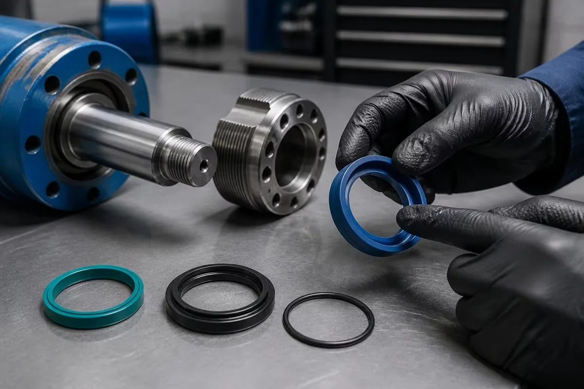
What Does Hydraulic Cylinder Seal Direction Mean?
Hydraulic cylinder seal direction describes the way a seal is positioned in its groove relative to the pressure side, the protected fluid, the rod, or the outside environment. Many dynamic seals have a working lip, sealing edge, energizing element, or pressure-activated profile. These features are not symmetrical even when the seal looks symmetrical at first glance.
As a practical rule, a primary sealing lip normally faces the pressure or fluid side that it is designed to contain. However, this is only a starting point. A double-acting piston seal, a rod seal with an energizer, and a dust wiper each work differently. The correct direction must be confirmed from the seal profile, the original installation, the manufacturer’s drawing, and the cylinder design.
Never assume that all U-cup seals face the same way. Never use the appearance of a seal from the front alone to decide its orientation. A wrong installation can produce leakage, pressure bypass, excessive friction, rod damage, or seal extrusion even when the dimensions are correct.
Pressure-Side Rules for Common Hydraulic Cylinder Seals
The following table provides a field reference. It is not a substitute for the cylinder manufacturer’s drawing or the seal supplier’s installation instructions, especially for custom profiles and high-pressure applications.
| Seal type | Primary function | Orientation check | Typical mistake |
|---|---|---|---|
| Rod seal | Controls fluid at the moving piston rod | Working lip normally faces the cylinder pressure side | Installing the lip toward the atmosphere |
| Piston seal | Separates pressure between cylinder chambers | Confirm whether the profile is single-acting or double-acting | Treating a double-acting profile as a one-way seal |
| Wiper seal | Excludes dirt, water, and debris from the cylinder | Wiping lip faces the outside environment | Reversing the lip and allowing contamination inward |
| Buffer seal | Manages pressure spikes before the rod seal | Follow the profile drawing and pressure-side marking | Assuming the buffer seal is interchangeable with a rod seal |
| O-ring and backup ring | Static sealing and extrusion support | Check groove position and backup-ring pressure side | Putting the backup ring on the wrong side of the O-ring |
How to Identify Rod Seal Orientation
Rod seals are installed in the gland around the piston rod. Their job is to retain hydraulic fluid as the rod moves while maintaining controlled contact with the rod surface. The pressure side is usually the side facing the inside of the cylinder, but profile geometry must still be checked.
Step 1: Photograph the old seal before removal. Before pulling the original seal from the gland, photograph its cross-section and position from several angles. Mark the cylinder head and the pressure-side direction with a paint marker. This simple record is especially useful when several seals look similar. Step 2: Identify the working lip. A working lip is often sharper, more flexible, or supported by a groove or energizer. The lip should not be folded, rolled, or trapped under the gland edge. If the profile has a pressure-activated cavity, the cavity normally belongs on the pressure side specified by the manufacturer. Step 3: Inspect the gland groove. Remove dirt, old seal fragments, and corrosion from the groove. A damaged groove can make a correctly oriented seal leak. Check that the groove width and depth match the replacement kit rather than forcing a different profile into the housing. Step 4: Confirm with the supplier drawing. For a B2B repair operation, the supplier should provide a profile drawing or installation diagram. Do not rely only on a product photograph because photographs can be mirrored or taken from an angle that hides the working lip.
Piston Seal Direction: Single-Acting Versus Double-Acting Profiles
Piston seal orientation is more complex than rod seal orientation because the piston may be designed for pressure in one direction or both directions. A single-acting piston seal is designed to seal primarily when pressure acts from one side. A double-acting piston seal must separate pressure as the cylinder changes direction.
For a single-acting profile, the pressure-activated lip or sealing edge normally faces the pressure side. Reversing it can cause internal bypass, slow movement, or failure to hold a load. For a double-acting profile, the geometry may use symmetrical sealing edges, a cap seal with an energizing O-ring, or a specialized profile that requires a defined installation position even though both directions are sealed.
When rebuilding an excavator boom cylinder, loader tilt cylinder, or backhoe stabilizer cylinder, identify the cylinder’s hydraulic function before choosing the piston seal. A seal kit selected only by outside diameter may contain the wrong pressure direction or profile. Confirm the bore, piston groove, fluid, pressure range, and operating temperature with the supplier.
Wiper Seal Direction and Contamination Control
A wiper seal is designed to keep external contamination out of the cylinder as the rod retracts. Its lip generally faces outward toward dust, mud, and water. If the wiper is reversed, it may fail to scrape the rod clean or may trap contamination near the rod seal.
For equipment working in quarries, demolition, agriculture, and mining, wiper design deserves particular attention. A double-lip wiper may provide a separate exclusion edge and support against the gland. However, more lips do not automatically mean better performance. The wiper must match the rod diameter, groove, environment, and expected rod speed.
A wiper should not be used as a substitute for a damaged rod seal. It also should not be installed with excessive interference that creates drag and heat. During inspection, check the rod surface, wiper lip, gland bore, and contamination path as one system.
Common Installation Errors That Reverse Seal Performance
Installing every seal with the lip facing the same direction
This shortcut ignores the different functions of rod seals, piston seals, buffer seals, and wipers. Each profile must be interpreted according to its pressure and contamination role.
Using a screwdriver on the sealing lip
Sharp tools can create cuts that are too small to notice during assembly but large enough to leak under pressure. Use rounded plastic picks, seal installation sleeves, and the tools recommended for the profile.
Stretching an elastomer beyond its recovery limit
Some seals must be expanded over a piston or compressed into a gland. Excessive stretching can permanently distort the lip. Follow the supplier’s installation method and allow the seal to recover before testing.
Ignoring the backup-ring direction
An O-ring and backup ring work together. Under pressure, the backup ring must support the extrusion gap on the correct side. A reversed backup ring can allow the O-ring to extrude even when the O-ring size is correct.
Using the wrong lubricant during assembly
The assembly lubricant must be compatible with the seal compound and hydraulic fluid. A lubricant that swells or softens the material can create a delayed failure after the cylinder returns to service.
Quality-Control Checklist for Repair Shops and Distributors
Before closing a rebuilt cylinder, use this checklist:
- Confirm the seal kit part number and dimensions against the cylinder application.
- Compare the new seal profile with the original and the supplier’s drawing.
- Mark the pressure side before installation.
- Inspect rod, bore, piston, grooves, threads, and gland edges for damage.
- Install each seal with the correct tool and compatible assembly lubricant.
- Check that wiper, rod seal, buffer seal, piston seal, O-ring, and backup ring are in the correct positions.
- Perform a controlled pressure and leakage test before returning the machine to service.
- Record the seal material, kit number, machine model, cylinder function, and installation date.
How a Factory Supplier Can Reduce Orientation Errors
B2B buyers should expect more than a bag of unmarked rings. A reliable hydraulic seal kit manufacturer should provide clear labeling, a profile drawing when needed, application cross-references, and technical support for unusual cylinder configurations. Kits for excavators, loaders, backhoes, cranes, and industrial cylinders may use different profiles even when some dimensions appear similar.
DJF Seals supplies hydraulic cylinder seal kits for distributors, repair shops, and equipment maintenance teams. When an application is unclear, buyers can provide the old seal, cylinder measurements, a part number, or a drawing for technical matching. The final selection should be based on verified dimensions and operating conditions rather than a generic visual match.
Conclusion
Correct hydraulic cylinder seal direction protects the seal lip, preserves pressure control, and reduces repeat repairs. The safest process is to document the original orientation, identify the pressure and contamination sides, inspect every groove, use the correct installation tool, and confirm the profile with a technical drawing. For B2B maintenance teams, this disciplined process is more reliable than guessing from a similar-looking seal.
For seal kit sourcing, contact DJF Seals with your machine model, cylinder function, part number, dimensions, or seal sample. Our team can help distributors and repair shops match the correct hydraulic sealing configuration for their equipment.
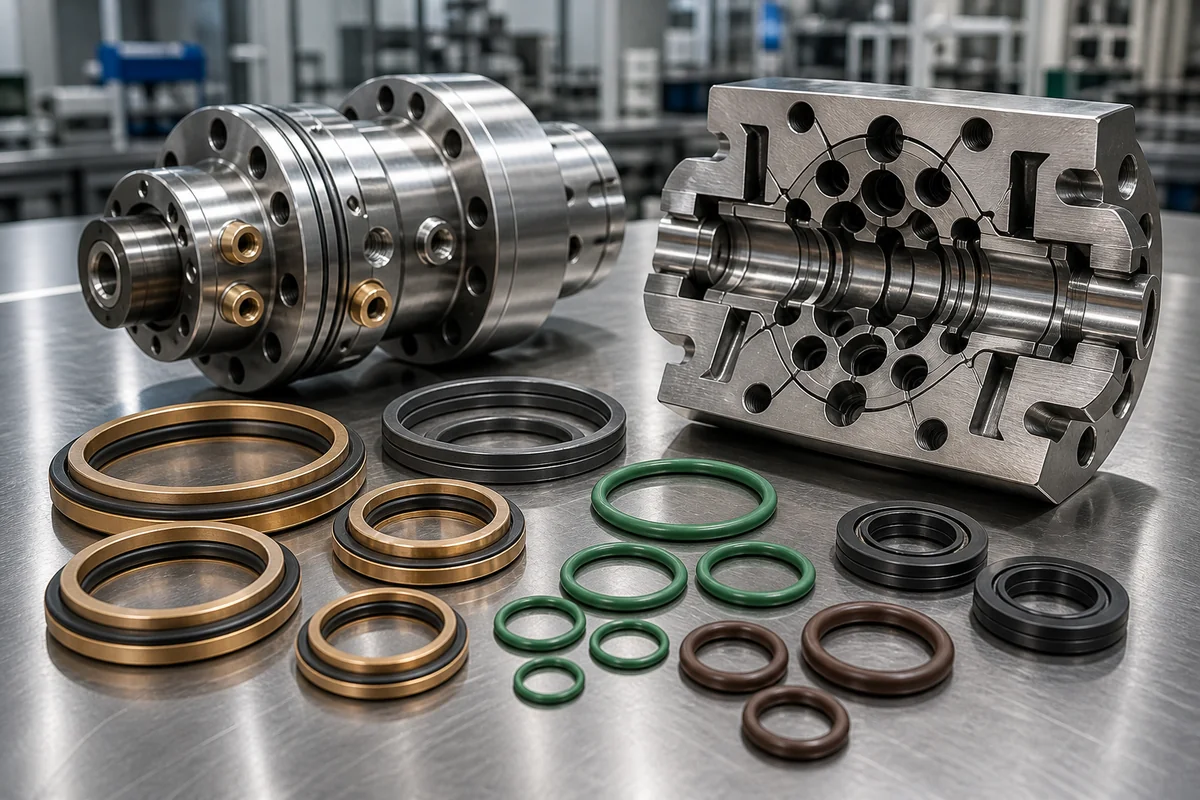 Excavator Center Joint (Swivel Joint) Seal Kits: Internal Cross-Port Leakage Troubleshooting, PTFE Step-Seal Selection & B2B Overhaul Guide
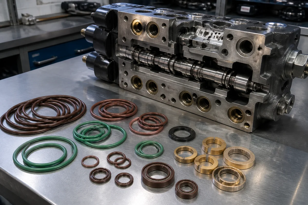 Excavator Main Control Valve Seal Kits: Spool Leakage Troubleshooting, Material Selection & B2B Sourcing Guide
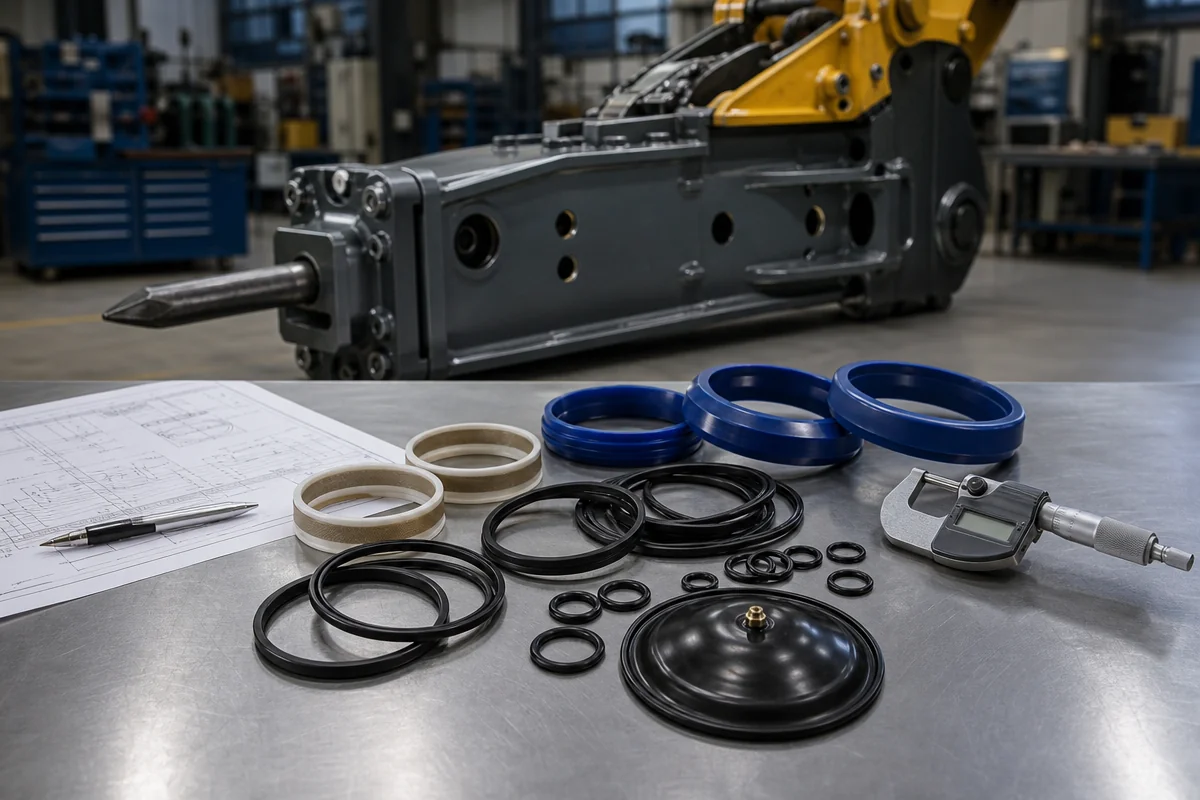 Hydraulic Breaker Hammer Seal Kits: B2B Sourcing, Material Selection, and High-Frequency Shock Protection Guide
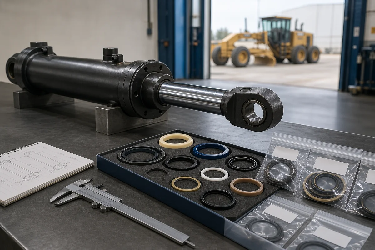 Motor Grader Hydraulic Cylinder Seal Kits: A B2B RFQ and Selection Guide